Knowledge / Ship systems
Seawater LT and HT cooling circuits
Why can a ship have seawater, low-temperature and high-temperature cooling circuits, and where does heat pass between them?
On this page
They serve different thermal duties and can keep different fluids apart. In a central-cooling arrangement, heat may travel from machinery into high-temperature freshwater, then into low-temperature freshwater, and finally into seawater. Heat crossing a heat-exchanger wall does not mean the two water streams mix. The actual connections depend on the vessel and engine design.
Read the names as functions
Seawater is commonly the final heat sink: it receives heat and carries it away. Low-temperature freshwater, usually called LT, can collect heat from lubricating-oil and charge-air coolers and from a jacket-water cooler. High-temperature freshwater, HT, can remove heat from engine jackets and associated hot components. These are representative duties, not a universal equipment list. Wärtsilä’s central-cooling overview describes this typical division.
“Low” and “high” are relative service descriptions. Neither label specifies an acceptable temperature, pressure, water treatment or alarm limit. A cooler may also have several stages assigned to different circuits. Engine documentation and the vessel’s actual piping arrangement determine those details.
Separating the seawater side confines its direct contact to a defined part of the cooling installation. Separate temperature levels also allow heat to be collected and rejected at different conditions. This does not make every freshwater component immune to corrosion or every circuit independent of the others.
Trace fluid and heat separately
A fluid-flow arrow says where mass travels. A heat-transfer arrow says where energy travels. In an ordinary surface heat exchanger, fluids occupy different passages; energy passes through the separating wall. The DOE heat-transfer handbook, module HT-02, pages 30–36, explains this physical distinction.
A mixing junction is different: streams enter a common fluid volume, so mass and energy balances both cross the junction. A heat exchanger symbol should not be read as a mixing junction. Conversely, calling two branches “HT” and “LT” does not prove that a wall separates them. The Wärtsilä 31SG product guide, section 9.2, discusses configurations in which separating HT from LT with a heat exchanger is an installation choice. That guide is an example of variation, not a template for other engines.
For any schematic, ask: which fluid is this line carrying, what boundary does it cross, and what evidence establishes the connection?
Trace the three separate paths
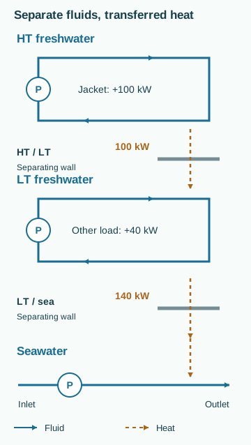
The teaching diagram keeps HT freshwater, LT freshwater and seawater in separate hydraulic paths. Solid arrows show fluid flow. Dashed arrows carry heat across an exchanger wall without joining the fluids.
Worked example with invented values
Suppose the diagram represents a steady teaching case. The jacket heat source adds 100 kW to HT water; another cooler adds 40 kW to LT water. Assume no heat recovery, external heat loss, fluid leakage or stored-energy change. Neglect pump heating. These assumptions are part of the example, not findings about real equipment.
Inputs:
- HT mass flow: 5 kg/s; freshwater specific heat: 4.18 kJ/(kg·K)
- LT mass flow: 8 kg/s; the same assumed specific heat
- Seawater mass flow: 7 kg/s; assumed specific heat: 4.00 kJ/(kg·K)
- Heat added to HT: 100 kW; direct LT heat input: 40 kW
For a single-phase stream with approximately constant specific heat, heat rate equals mass flow × specific heat × temperature change. Here kJ/s equals kW. A temperature difference of 1 K has the same magnitude as a difference of 1 °C.
The HT water gains 100/(5 × 4.18) = 4.78 K across its heat source and loses the same temperature difference across its cooler. The HT/LT exchanger transfers 100 kW to LT water without transferring HT water into that circuit.
The central exchanger receives the accumulated LT duty: 100 + 40 = 140 kW. LT water therefore cools by 140/(8 × 4.18) = 4.19 K through that exchanger. Seawater warms by 140/(7 × 4.00) = 5.00 K.
Outputs are three temperature changes and two exchanger duties. They are not absolute inlet temperatures, equipment capacities or recommended operating values. Equal heat rates do not require equal mass flows or equal temperature changes.
The 100 kW passes through two successive boundaries. Adding 100 kW at the first exchanger to 140 kW at the second would double-count part of the same energy. For the complete installation boundary, external heat input and seawater heat rejection are both 140 kW under the stated assumptions.
What this balance leaves unresolved
The arithmetic establishes an energy requirement. It does not establish whether either exchanger can transfer that duty at the available temperatures. Surface area, transfer coefficients, fouling, flow distribution and temperature differences still matter. A mathematically balanced example can demand a physically unattainable heat transfer.
Actual inlet and outlet temperatures, rather than temperature changes alone, are also needed to check heat-flow direction. A higher heat load or warmer sea can change achievable conditions; the words LT and HT alone do not predict the result. During transients, energy can accumulate in the water, engine structure and exchanger metal, so instantaneous inlet and outlet heat rates need not match.
A bypass changes distribution without removing the heat duty
A temperature-control arrangement may divide flow between a cooler and a bypass before the streams rejoin. For an ideal same-fluid, steady mixing example with negligible external heat exchange, mixed enthalpy is the mass-flow-weighted average of the inlet enthalpies. If specific heat is approximately equal and constant, the same weighted relation can be written using temperature. Valve position alone does not establish the two mass flows because each branch has its own hydraulic resistance.
Suppose an invented 10 kg/s freshwater stream divides into 6 kg/s leaving a cooler at 30 °C and 4 kg/s bypassing at 50 °C. The mixed temperature is (6 × 30 + 4 × 50)/10 = 38 °C. The cooler removes 6 × 4.18 × (50 − 30) = 501.6 kW on the stated assumptions. Applying the same calculation to the full flow and the mixed outlet gives 10 × 4.18 × (50 − 38) = 501.6 kW. These are two boundaries around the same duty, not two duties to add.
Distinguish thermal adequacy from hydraulic availability
The DOE heat-transfer handbook explains that exchanger duty depends on the temperature driving force as well as transfer capability. Warm seawater can reduce the available driving force even when the pumps and valves remain in their usual configuration. Conversely, a suitable sea temperature does not establish adequate flow through the cooler. The thermal and hydraulic questions must be answered together.
A useful comparison holds the relevant load and operating state as nearly comparable as the evidence permits. Record all inlet and outlet temperatures, flows if available, control state and sea conditions. A higher LT outlet temperature by itself does not distinguish increased machinery load, reduced seawater flow, fouling or changed bypass distribution. The goal is to narrow the explanations with evidence, not to rename every high temperature as a dirty cooler.
Maintenance can change the shared heat-rejection path
Two freshwater circuits may be hydraulically separate but depend on one final heat-rejection path. Isolating a central cooler for maintenance can therefore affect several consumers. Assess the remaining arrangement at the required simultaneous duty, rather than evaluating each consumer as though it were alone. An available spare component is not necessarily a ready substitute if the required valves, power or control mode have not been restored.
The Wärtsilä central-cooling overview provides a typical circuit division, not a universal redundancy scheme. An engineering dependency map should distinguish a shared exchanger, a shared seawater intake and a shared electrical supply. Each can defeat different apparent redundancies. Use the actual approved arrangement to decide which loss conditions must be demonstrated; the generic drawing in this article does not establish those requirements.
Interpret leakage and water condition with the correct boundary
A leak across an exchanger wall creates a mass-transfer path that the ideal thermal diagram excludes. Its direction depends on the pressure difference under the relevant state and may differ between operation and shutdown. Temperature agreement alone does not prove hydraulic separation. Investigation requires the installed design, fluid-condition evidence and approved safe procedures; this article does not propose a pressure test or chemical-treatment recipe.
Keep expansion, venting, make-up and water treatment in the real system description even though the teaching diagram omits them. These functions influence inventory, pressure and long-term condition. Omitted detail should remain visibly omitted; it should not become an assumption that the function is unnecessary. That boundary discipline lets the simple heat-path model remain useful without turning it into a construction drawing.
Common mistakes and useful outputs
Avoid treating a shared thermal path as a shared fluid path, assuming all HT heat reaches the sea when heat recovery exists, or claiming that a running pump proves adequate flow. Do not diagnose fouling from one high temperature without considering heat load, flow, measurement quality and the actual arrangement.
A useful study output contains the fluid boundaries, heat sources and sinks, assumed state, flow and temperature units, calculation boundary and unresolved evidence. Real design and operation require the applicable installation documentation and qualified engineering review. This guide provides no operating procedure, safety setpoints or compliance conclusion.
Related guides: Cooling-system heat balances; Pump curves and system resistance; Heat-exchanger capacity and approach temperature; Sensor reading, control command and physical state.